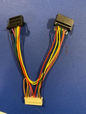
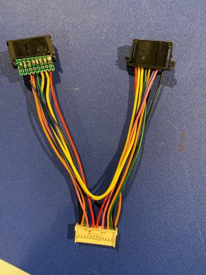
AP1 Harness
From Tinkla: Tinkering with Tesla
Contents
Parts Needed
For the best experience, just purchase our Tinkla OBD-C Adapter for Tesla Model S with AP1 for $125 from our online store
or
build your own for about $220 + tools and a lot of crimping :)
- A Comma Car Harness for Development Vehicle - $200.00
- 1 x TE Connectivity/AMP 1-1743284-2 - $4.42
- 1 x TE Connectivity/AMP 1-1743282-2 - $1.08
- 8 x TE Connectivity/AMP 5-963715-1-CT - unfortunately you can only by them in strips of 100 for $9.10
- about 20" of #18 automotive wire
The PCB Board
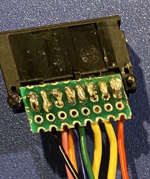
- As you can see from the parts list, I did not find a male connector that has pins. This one is designed to be used in a PCB board. I had a development PCB board in my workshop, so I just used some string scisors and cut it to fit. If you don't have one, you can order one from Amazon or pick one up from your local electronics store, like MicroCenter.
- The best way is to go with the wires and the connector from the same side of the PCB board, the solder on the back. See picture of how my PCB board looked once I soldered it all together.
The Comma 26 Pin Connector
- Take your time and use a sharp object to take out all the wires that you are not using from the 26 pin connector of the Comma harness. Will make everything look better and fit better under the roof liner.
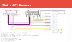
- Pay extra attention at the jumper that comes with the harness between the pins 3-5. We need to reuse that one and insert it between the pins 23-25.
The Defrost Power
- The AP1 hardware gets 10A @ 12V power just to be able to defrost the windshield in front of the camera.
- The wires that come with the Comma car harness are too thin to handle so many amps.
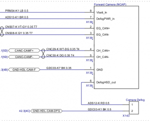
- Use the #18 wire from the parts list to connect pins 6 (Defog to windshield) and 7 (Defog power in) from the male connector to the female connector.
- Do not use the Comma harness wires for this!
Making the Harness
- Solder and crimp the wires per the diagram above
- Note the connector orientation and the pin numbers
- Make sure the connections are well done and no wires are lose
- Test with a voltmeter if possible between each corresponding pin of the two black connectors
